Form Printer is Gone

I parted ways with my Form1 yesterday. It’s going to a good home here in California, Michael Balzer, someone who really wanted to get it up and running ASAP. He has some neat services / items @ http://slo3dcreators.com/ 
Can’t wait to see how these printers evolve in the future and maybe I’ll pony up again once they get gray resin working 🙂

Replacement Printer Results

With my first Form printer showing serious problems when trying to print the Eiffel tower model I was approved to return the printer and received a replacement.  It arrived on monday the 12th and I was up and running with a fresh bottle of resin.

I used the same lower half of the two part tower that I did in the original post:

https://www.dropbox.com/s/xbwk5mui441b1cv/eiffelPart1.stl

I’m using the first picture to establish an arbitrary coordinate system with X being parallel with the power button panel and Y perpendicular to the X.  The reason I’m doing that is I saw a very clear asymmetry to my second attempt of the tower.geometry

The long edges that ran parallel with the X axis (where the Y movements would be very small) look fairly decent.  But the edges that run parallel to the Y axis showed some of the same gross failures I saw with the first printer.  The diagram below details the four different long edges.  Edge “1” would be the long features closest to the power button face.

sides

Edge 1 face:IMG_1366

Edge 1 face from below:

IMG_1360

Edge 1 face front view:

IMG_1368

Edge 2 face:

IMG_1363

Edge 2 face from below:

IMG_1375

Edge 2 face front:

IMG_1369

Edge 3 face:

IMG_1364

Edge 3 face from below:

IMG_1361

Edge 3 face front:

IMG_1370

Edge 4 face:

IMG_1365

Edge 4 face from below:

IMG_1362

Edge 4 face front:

IMG_1367

Top View:   IMG_1371

Bottom View:IMG_1372

Interesting Comparison

Last week I was really excited to get my Form1 printer and start printing.  I came up with a calibration piece that really tested the precision and accuracy of the printer ( http://wp.me/p3MPgj-2 ).  One of the comments I got from that post was from Mike Joyce.  He asked for a copy of the calibration piece and next thing I knew he had printed it on one of his B9 creator devices.  Then he reaches out to send me the piece to show me the results first hand.  I got it in the mail yesterday and today I took a look at the print.

I don’t know if the print was a bit damaged when it was sent because there’s a little bit of a dimple in one of the long edges and the base.  The pictures that he shared with me didn’t seem to have the same defect.  The material itself is interesting.  It has the tactile feel of wax and a strong press with a fingernail leaves an indentation.  It is unlikely that a material like this would hold up in a mechanical prototype but I’d be interested to hear what people have been able to accomplish.

IMG_13203de05-DSCN2618

This is the picture Mike posted on his forum right after it printed ( http://b9creator.com/support/?mingleforumaction=viewtopic&t=705.0#postid-7109 ).  I love the geometry of the supports!

I was really intrigued to see that several of the very small features.  I had arrayed out a grid of 500 micron through holes and 15 of the 16 printed all the way through the piece!  300 micron features also printed very nicely.

IMG_1319

The small slot feature 4mm x 0,5 mm also printed well.

IMG_1317

IMG_1316

It did very nicely on all of the basic dimensions 25X25 mm was 25.02X25.07.

IMG_1313

IMG_1312

The 23mm diameter circle measured 22.94X23.02mm in the x- and y- axes (they are arbitrary since I don’t know how the piece was printed on the device).

IMG_1314 IMG_1315

All of the other dimension seem to be close to the optimal (I admit I haven’t measured all of the dimensions at this point).        2

3

4

5

6

7

Holding Pattern

After sharing the results of the Eiffel Tower print with the formlabs team they’ve concluded that there is a problem with the printer that needs to be diagnosed at HQ.
They promptly provided packing instructions and a shipping label. I dropped it off this morning at FedEx. Hopefully they will be able to learn something useful from this unit.
Until I get another printer in hand I won’t be posting any more prints.

Pièce de résistance

eiffel full

The reason I got a Form printer is quite simple, the Eiffel tower print featured in the Kickstarter video sealed the deal for me.  The tower features curves, fine railing elements, and details I can’t achieve on my ABS printer.

I reached out to Formlabs to provide me with the settings and model they use to print the tower.  I got a two part STL model that is based on a Thingiverse/GrabCad model:

http://www.thingiverse.com/thing:24068

The STL I used directly from Formlabs can be found here:

https://www.dropbox.com/s/xbwk5mui441b1cv/eiffelPart1.stl

https://www.dropbox.com/s/k6e05q7uy9el1aq/eiffelPart2.stl

Prepare yourself for a long print if you try Part1.  PreForm calculated 83 mL of resin and over 11 hours of printing.  One thing I think this print might have uncovered is a timing bug.

If you watch the movie below of the build plat form deflecting you’ll see that the printer is work on layer 48 of ~2100.  It calculated that are 10 hours 21 minutes left.  That was at 1:49 PM.  But if you watch the finishing movie you’ll see the print didn’t actually finish till the following morning at 7:39 AM.  I didn’t watch it through the night to see if it recalculated the timing but it seems a bit mysterious that the timer was off by a good ~7 hours.

Okay back to the printing of the tower.  I used all of the default settinsg per the advice I got from the Formlabs support team (Sam has been super helpful and responsive trying to help me get the printer up and running).  I also got advised that I could print the tower without any support structures which is very exciting.  I’d been thinking that if your piece had good surface contact with the build platform and no overhangs that you might be able to print without supports and I’m glad to report that this seems to be the case with the tower.

Capture

This was the first glimpse of the print coming out of the resin:

IMG_1280

Everything seemed to be going smoothly but I began to notice something that I didn’t see with my test calibration piece.  Every once in a while during the peel step the build platform would get pulled out of position and then bounce back into place.

http://www.youtube.com/watch?v=g-7YQidMYr4&feature=youtu.be

Then at about 7:30 in the morning the print finished:

http://www.youtube.com/watch?v=yrvaHin1ZhI&feature=youtu.be

My first impression was that something didn’t look quite right around the lower arch of the tower:

IMG_1285

So I took the model off and went through the standard rinsing, washing, and incubating in 99% IPA.  With a model this big it would sure be nice to have a large rinsing tub because with the tub pretty much the same dimensions as the build platform it’s a tight fit.

While it was drying I started taking some low resolution pictures of the tower.  You can see on the arch where you’d expect so see a nice smooth curve there are all sorts of spikes and disruptions in the model

IMG_1293

I took the STL and measured a couple of the easier dimensions.  The base of the tower measures out to be 120X120mm.  The print does well, 120.6 X 121.3.  I would have been happier if I hadn’t see the now consistent discrepancy between the X- and Y-axes.

dimensions IMG_1302 IMG_1301

I also took some measurements from the mid-deck platform where the model shows 37 x 37 mm.  Things are looking pretty good with 36.73 x 37.51.  The same bias with the Y-axis longer than the X-axis.

top dimensions  IMG_1304  IMG_1303

But now we get into some of the really troubling parts of the print.  The supports in the legs have very inconsistent widths and appearance. 8

710 

There are also huge sections of the model missing under the lower deck.  It seems like the print was only able to keep going because other parts of the model were strong enough to keep the entire structure together.  It’s hard to tell how this kind of failure is occurring because the structure fails but then it starts to print again and eventually forms back into a well formed railing.

3

4

I’ll be sharing these results with the form team but it seems like the printer is fully in the close-but-not-quite mode for the time being.

Form1 Printer Results

calibration iso

I was immediately enthralled with the idea of getting my hands on a high quality SLA printer that could produce a model of the iconic Eiffel Tower.  Each time I saw that print in the Kickstarter movie I envisioned making models of all of my favorite architectural landmarks.

In preparation of my printer and resin arriving I put together a calibration piece so I could get some sense of the accuracy and precision that I might take advantage of with the printer.  This piece was inspired by the diligent and thoughtful work of two other form owner’s:

http://exploreideasdaily.wordpress.com/2013/07/12/episode-2-form1-calibration-strikes-back/

and

http://adventuresin3dprinting.blogspot.com/2013/06/success.html

I’ve been printing with an Up! since 2009 and have loved every minute except for not being able to print small features.  That’s what really drew me to the form, Form-1-Tech-Specs, because they continue to publish that the Form1 can make a 300 micron feature.  So this calibration piece was designed to test those specifications.

Here are some of the highlights of the test piece:

calibration piece

25 X 25 mm square base

23 mm diameter circle on the base

Several smaller squares 3×3, 4×4, 5×5, 6×6 mm

Several cylinders with diameters ranging from 0.5 mm to 4 mm

Slots with opening of 0.5 mm and 0.3 mm

There are a few more features that are designed to test the Z dimension but I’m not going to cover those in these results.

I loaded the piece into the form software with all of the default settings and setting for clear resin:

ready to form with default settings

Everything started up just fine and the printer was humming along.  The print finished and I opened up the lid to see a piece that looked pretty nice.  But then my eye caught a straggler of resin hanging off the side of one of the supports.  It was impossible to tell where the piece came from and it wasn’t very large.

IMG_1250

So I pulled the piece off the base and washed it in 99% IPA with 2 minutes of shaking and 8 minutes of soaking.  Then I pulled the piece out and got down to measuring.

One of the things I’ve been most anxious about since reading the detailed post, http://exploreideasdaily.wordpress.com/2013/07/12/episode-2-form1-calibration-strikes-back/ , was the concentricity of round features.  Sadly, I’m seeing the same defective printing on my machine along the X-axis the 23 mm circle measures 22.86 mm and along the Y-axis the 23 mm circle measures 23.11 mm.  These mitutoyo have served me well in the past and I have every reason to believe the ~0.25 mm difference is real.IMG_1254

IMG_1255Then I pulled out the USB part inspection scope to look at some of the smaller features at higher magnification:

The 0.5 mm wide slot measured in at 0.75 mm, which is pretty good.  But the big disappointment is the 0.3 mm slot was completely occluded.  You could see where the laser was trying to draw the slot but it just couldn’t create the opening.  You can also see some heterogeneity in the surface, I’m not really sure where that comes from because the standoffs were all attached to the other side of the piece.

slots

Then I looked at some of the other small hole features:

The width of the square was supposed to be 5 mm and depending on where you measured from it was pretty close ~4.4 mm.  Most of the square elements had a bit of a draft to the feature that I haven’t quantified yet.

But again my big disappointment with the printer is that it’s advertised to be capable of printing a 300 micron feature.  Here I had a grid of 500 micron holes and the radii were measuring at ~300 microns with all of the holes fully occluded (they are designed as through holes).

holes

Now, onto one of the printed columns:

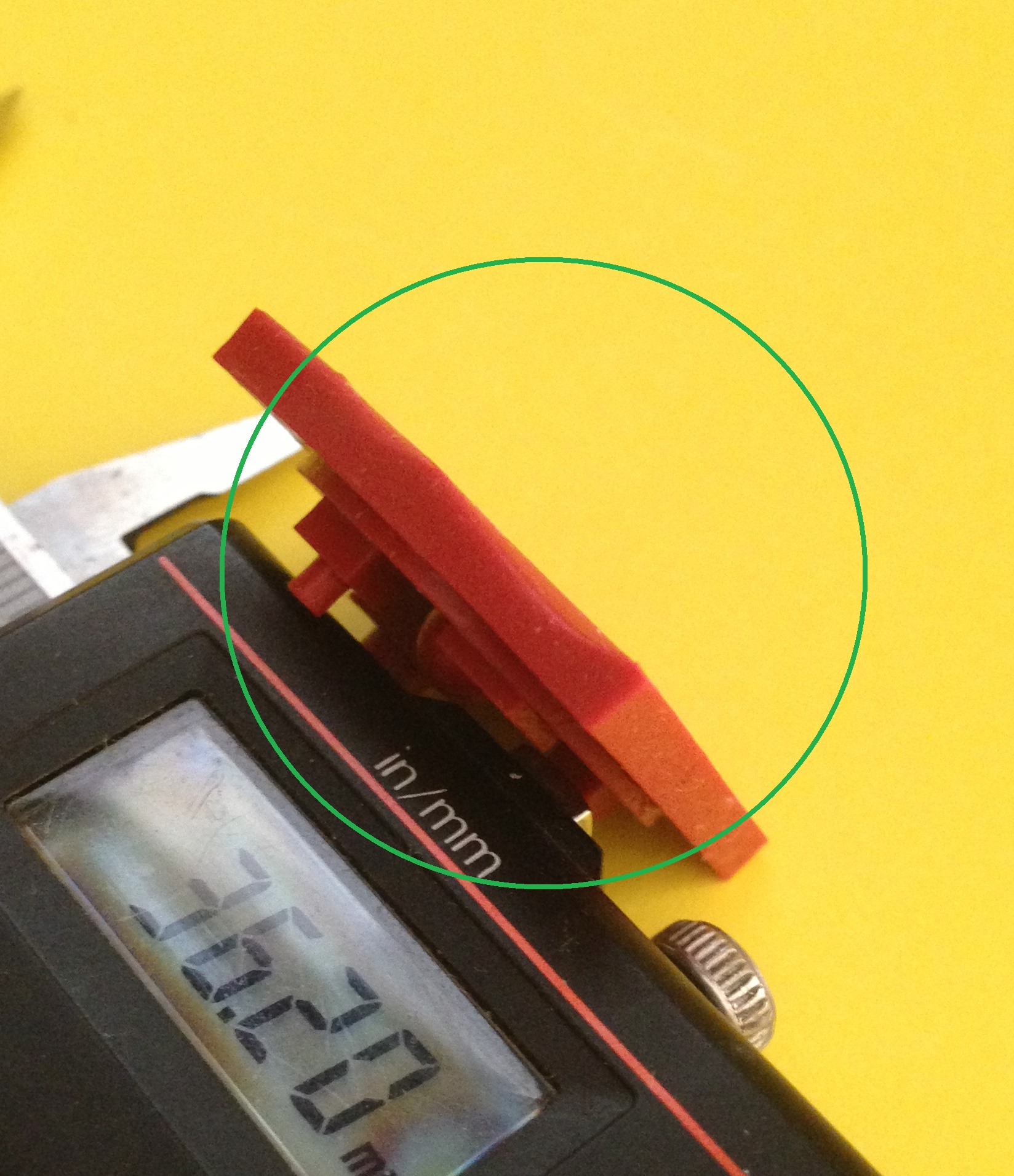
The square base was supposed to be  4×4 mm, it measured 3.17X3.41 mm which again could be slightly off because of the draft that was present in the feature.  The inner diameter of the tube was supposed to be a whopping 1.4 mm!  It measured 1.6 mm, but the resin also cured to fill up the tube and not leave it hollow.

single hole

Then I broke out my trusty Generation 1 Up! printer to make the part out of ABS.

IMG_1262

The results were pretty much exactly what I’ve come to expect from this workhorse.  The 25 X 25 mm square was 25.02 X 24.92.

IMG_1259

IMG_1258

But more importantly the 23 mm circle was within the same tolerance, 22.93 x 22.9

IMG_1261

IMG_1260

The smaller features were less accurate, but that’s why I signed up to buy the Form.  The 5×5 was 5.44X5.85.

hole with cylinder

The 3×3 was 2.75 x 2.81

3 mm feature

And the 4×4 was 4.2×4.4.

holes

It was suggested to me that I try printing the calibration piece on the Form with the flat surface parallel to the building platform.  I tried that but the first thing I noticed is that the flat surface is now going to require a ton of elbow grease to get flat because of all the marks left from the support pillars.

flat printed calibration piece

IMG_1257

IMG_1256

I let the piece cure in the San Francisco sun

IMG_1270

And then after removing the supports I was left with this mess:

IMG_1271

It’s hard to describe what the surface is like except to say that it’s non-uniform and would require some diligent sanding to achieve anything close to a flat surface.

back surface 1

back surface 2

Some of the features turned out a bit better but the back surface was such a mess it doesn’t seem like it’s worth the trade-off because the 300 micron features still failed in this orientation.

new slot

Maybe this printer will turn out to be okay for asymmetric pieces but I purchased it for the advertised 300 micron feature size so I could use it for prototyping intricate mechanical devices, similar to the flow cell advertised in the Kickstarter video.